|
Recovery and Restoration of a T1509 Transmitter part 5. February 2005 Power-Up! |
|
|
I pondered on
the electrical supply problems for several days, contemplating
connecting two power tool transformers back to back. This was
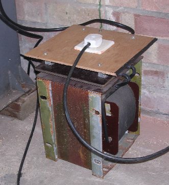
discussed on air and Dave, G8SFU came up with a solution - the 5kVA
isolating transformer shown here, strictly on loan! It was duly delivered to the
Horncastle rally and heaved from the back of one van to another - it
weighs around 1cwt. The piece of plywood and 13 amp socket were
added by me - it had exposed large brass terminals on top, I thought it
better if they were covered over.
I plugged it in, applied power and there was a loud 'klunk' and humming noise and the lights came on, probably for the first time in almost 40 years - what excitement! I thought 'what the heck' and turned the control selector to 'test' - this keys up the tx in cw mode for tuning. Another klunk and the power to the shack went off again! Investigating the distribution board, I saw that the single socket was supplied from a 10amp MCB that also supplied the lights. More discussion with Dave
revealed that there are various types of MCBs, a 'type D' was what we
needed, one intended for motor supplies, a sort of 'antisurge'
type. I now needed to get permission to upgrade the electrical
system before I could do anything further. |
|
I decided to
remove the MO (master oscillator) unit - VFO to the more modern amateur
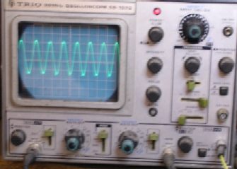
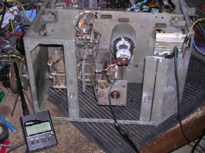
- and take it home to check it out. This itself is a massive structure, with two roller-coasters, the oscillator itself is an 807, more familiar as a PA valve to the real radio amateur, and is fed from a network of four CV45 voltage regulators and with its heater supply stabilised by a thermistor and barretter from a separate 14 volt AC winding on the LT transformer. Here was a problem - I have not succeeded in obtaining a barretter (type CV2734), and the thermistor had crumbled to dust, as had some of the rubber insulated wiring in the area - it obviously runs very hot! < The MO unit during bench testing. Power was again filched from the old Linear Concord amplifier, It was running when the picture was taken - the frequency counter (if you can see the display in this reduced resolution photo) shows the frequency as 3.625kHz. The output looked to be a very nice sinewave, as seen here. I decided that, at least temporarily, I would take the coward's way out and build a solid state regulator. The 14V AC supply is rectified and stabilised to 6.3 volts for the 807 with a simple 2N3055 series regulator. The heatsink for this can be seen on the right, mounted above the barretter holder in the picture. The decomposed rubber wiring to the power supply plug was also replaced at this stage.
|
 |
Another
item that needed attention was the source of that loud humming when the
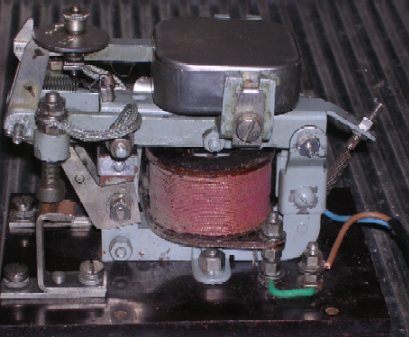
unit was initially powered. It seems that if the transmitter is keyed before the valves have fully warmed up there is the possibility of damage to the rectifiers, so the manufacturer incorporated a 'delay relay' in the supply to the HT transformer. Not your ordinary common thermal delay relay, oh no - this one is a massive contactor incorporating a sort of clockwork mechanism to provide an adjustable delay of 10 - 30 seconds. This unit was also removed and taken home for examination. What a masterpiece of engineering! All it needed was a good clean and adjustment and the armature rattled its way home and was then nice and silent. It was adjusted to give a 20 second delay. <Here the mains voltage coil can be clearly seen. Mounted on the armature above it is the plated brass box containing the 'clockwork' delay mechanism, the quality of which is equal to many an antique clock.
|
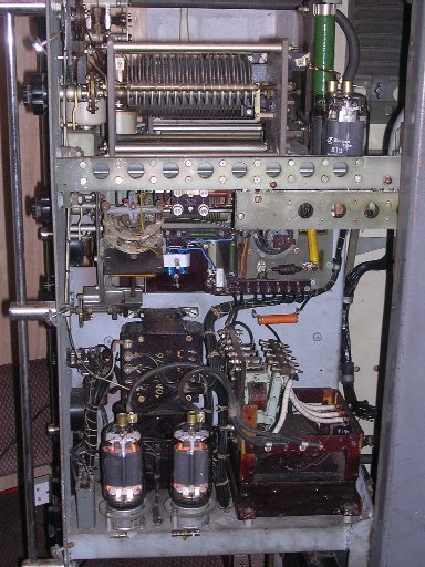 |
By the time of the next visit I had acquired a 32D MCB. After re-fitting the MO and relay units, I temporarily fitted this into the distribution board. I again powered the transmitter and waited the 20 seconds , this time when I keyed it, it went off altogether, the result of two blown 13 amp fuses! To cut a long story short it turned out that one of the U19 rectifiers was defective, though there was no measurable short, or visible damage. With a replacement fitted I could key up without anything popping off - and there was some indication of output power. I went home very excited that day. Next we had to get it tuned up and some audio applied..... < Here is a view of the transmitter - power is applied and the 813 valves are pretending to be electric lamps! |