|
Recovery
and Restoration of a T1509 Transmitter part 2. December 2005 |
|
 |
The next trip
to Thorpe Camp was on December 10th 2005, to have a look at the beast in
daylight, and to see what I'd really let myself in for. It was a freezing
cold morning, so I took a fan heater and my GRC9, with a view to calling
into the VMARS net as well. The heater and the GRC9 were both
connected up, the net was in full swing with 5&9 signals from
everyone, but no matter how many times I called, no-one heard me.
The neon glowed brightly on the GRC9, but I had no other test gear with
me so I assumed that either I was tuned up incorrectly or everyone else
had cloth ears. The fan heater wasn't making the slightest
difference to the air temperature either. The exhaust fell
off my car on the way to TC as well - so far things were not looking
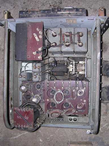
good! Keeping my hat and gloves on and hoping for better things I turned to the T1509. The PSU was minus most of its valves, and at this point I also spotted that two of the rectifier bases had been changed from the correct B4 type to octal. They were wired for two fullwave rectifiers in parallel. I have not been able to find any octal rectifier with a 4 volt heater that would run with 550V AC on its anodes, so I can only assume that the perpetrator of this crime had used 5 volt types such as 5R4's and underrun them by 20%. I suspect they would have had a short life. This would have to be restored to original, no problem as I had a plentiful supply of U19's by now. Two of the fuse holders were broken too. I made a note in my book to obtain a pair of B4 sockets and some fuseholders. Otherwise the PSU looked OK. It wasn't till later that I discovered that I had the GRC9 connected to the 20m beam, and the element in the heater had gone o/c. < Top view of the Power Supply Unit. The non-standard valve holders can be clearly seen. |
 |
Turning next
to the cabinet, it was clear that there was some damage to the wiring
loom, and the rubber insulated wiring had perished. This, of
course had to be the high voltage wiring, so would need
replacement. The entire loom was stripped from the cabinet and put
in the back of the car to be re-wired in the comfort of the home QTH.
The fan was removed too for checking.
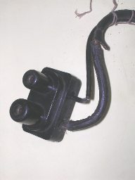
<This is the plug that carries 550 and 1600 volts to the transmitter - the split and perished wiring can be clearly seen. |
 |
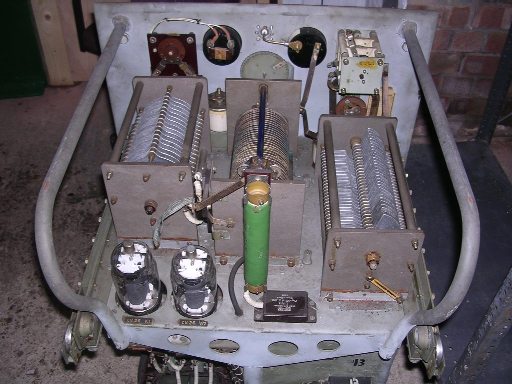
A
look at the RF unit revealed that most of the controls were seized, two
of the slydlok fuseholders on the front were broken and the valve top
caps were missing but it otherwise looked in good condition.
In the bottom right of this picture you can see the HT contactors (relays) - they were designed to last! The 813's were put in temporarily for the photograph. You can judge the scale of the thing if you remember that these valves are almost the size of a milk-bottle! |
| < Side view of the RF unit | |
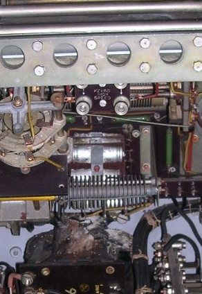 |
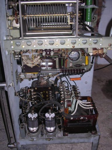
A
closer look at the unit showed that all six of the electrolytic
capacitors in the centre of the picture had at some time in the past
blown their ends out and deposited their contents on the
transformer below. These are the smoothing caps for the grid bias
supply. Meter tests showed that the rectifiers (in front of
the caps) were OK. A note was made to obtain some replacement
capacitors (each 8uF 150 volt.) and some WD40 to deal with the controls.
<Closeup of the bias smoothing capacitors. |